Buoy-Bot build guide
Reproduced from the project's own build guide. Drawings and stage renders are the generated originals. The itemised parts list, the wiring guide and the carrier-board documentation are kept with the project and are not published here — references to them appear below in plain text.
Step-by-step instructions for building one Buoy-Bot hull on a home workbench with a drill, a saw and a soldering iron.
| Applies to | hull design revision 3 of 2026-10-03 (834 mm hull; two stock 6 Ah battery packs; 180 mm marker; rubber-cap hatch; split strut; sled seated on the strut stubs; ballast potted only after the float test); carrier PCB rev B |
| Units | millimetres unless a pipe or thread size is quoted in inches |
| Buy first | PARTS_ORDER.md |
| Why it is built this way | BUOY_PHYSICAL_DESIGN.md |
| Wiring reference | WIRING_GUIDE.md, ../hardware/sled-carrier/ |
| Source of every dimension | design/buoy_dims.py — the drawings, the 3D model and this guide all read from it |
Contents
- What you are building
- Before you start: directions, schedule, cure times, safety, tools
- Day 1 — 1 Hull pipe ·
2 Bottom cap · 3 Pod end caps · 4 Strut stubs
- Day 2 — 5 Hatch cap ·
6 Sled · 7 Masthead · 8 Pods onto the stubs
- Day 3 — 9 Pressure test ·
10 Ballast, loose · 11 Battery · 12 Final assembly · 13 Bench test · 14 Seal, calibrate, float trim
- After the float test — 15 Pot the ballast, first water
- Appendices: A Opening it up ·
B Routine checks · C Building without the carrier PCB · D Troubleshooting · E Dimensions on one page
What you are building
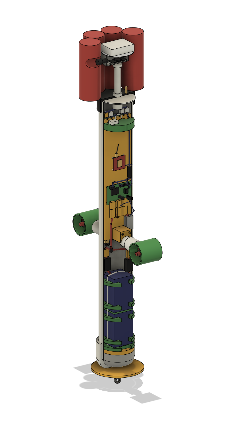
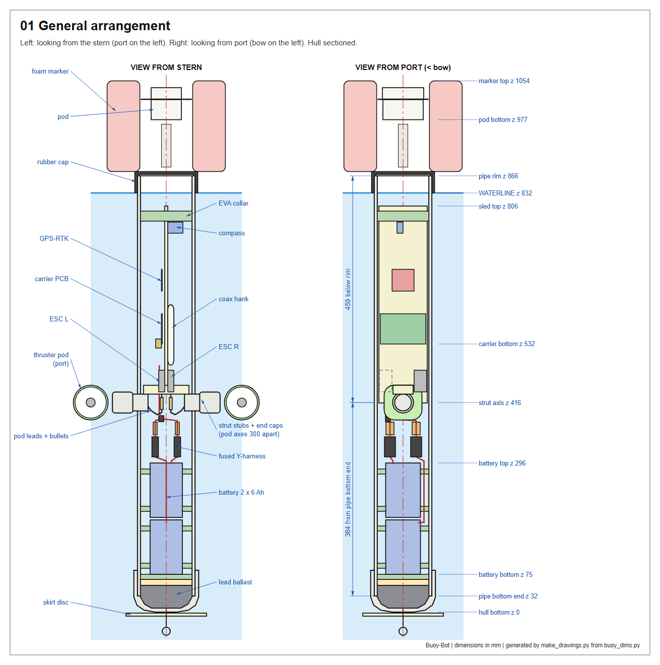
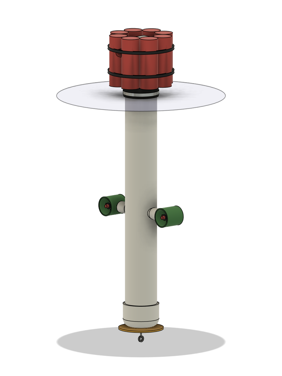
A spar buoy: a vertical 4" PVC pipe, ballasted at the bottom, floating with its top just above the water. Two thrusters, one each side, hold it on station. It is made of three modules that separate with one screwdriver:
| Module | What it is | When you service it |
|---|---|---|
| Hull | 834 mm of 4" PVC pipe; bottom cap with lead ballast; two strut stubs carrying the thruster pods; the battery | stays put |
| Sled | a 96 × 391 mm plate carrying both motor controllers (ESCs), the carrier PCB, the GPS board and the compass. It sits on the strut stubs inside the pipe | lifts out |
| Hatch and masthead | a rubber cap clamped over the pipe rim; a short flexible stalk; the pod (Feather, antenna, charge/ON connector); the red foam marker | lifts off |
Two sets of connectors join the modules: four small ones just under the hatch, and the battery plug plus six motor bullets at the foot of the sled. Long service loops let the sled rise to the rim before anything is unplugged, so nothing ever has to be reached down the pipe.
Two things about the design shape the whole build:
- The strut is two stubs, not one tube. The battery lives below the
thrusters and has to pass them on its way in and out, so the middle of the pipe is left clear.
- The lead is not glued in until the buoy has floated. The right
amount of ballast depends on what your parts really weigh. It goes in as loose shot in bags, is adjusted at the float test (step 14), and is potted only then (step 15).
Before you start
Directions
The buoy has a bow: the direction the thrusters push it. Everything is referred to four words.
- Bow / stern — front / back. Step 1 draws a BOW line down the
pipe; it is the reference for everything else.
- Port / starboard — left / right for someone standing behind the
buoy and looking toward the bow.
The strut stubs point to port and starboard. The sled plate stands on edge along the bow–stern line, so it has a port face and a starboard face. Looking at the port face, the bow is on your left; looking at the starboard face, the bow is on your right. Every drawing says which way it is looking. Write BOW, STERN, PORT FACE and STBD FACE on the plate as soon as it is cut.
Where measurements start
The bottom cap's dome differs between brands, so this guide measures from the pipe's own bottom end or its top rim. (The drawings also give z heights above the finished hull bottom, for reference.)
Schedule
About 14 hours of work. The days are set by cure times, not by effort.
| Day | Steps | Work | Left to cure overnight |
|---|---|---|---|
| 1 | 1–4 | pipe, bottom cap, pod end caps, strut stubs | cap weld, pod potting, stub epoxy |
| 2 | 5–8 | hatch cap, sled, masthead; pods cemented on last | masthead potting, pod-cap welds |
| 3 | 9–14 | pressure test, loose ballast, battery, assembly, bench test, float trim | — |
| 4 | 15 | pot the ballast | ballast epoxy |
| 5 | 15 | reassemble, re-check, first water | — |
Cure times
| Joint | Minimum before the next operation | Before a pressure test |
|---|---|---|
| PVC solvent weld, 4" cap | hold 30 s; 2 h before handling | 24 h |
| PVC solvent weld, 1" caps | hold 30 s; 15 min before handling | 24 h |
| Slow epoxy (potting, ballast) | 24 h | 24 h |
| Epoxy putty fillets | 1 h | 24 h |
| Marine sealant | per the tube, typically 24 h | 24 h |
Cold slows everything: below 15 °C, double these.
Safety
- Solvent cement and primer: outdoors or strong ventilation, gloves,
no flame.
- Lead shot: nitrile gloves, no food or drink on the bench, wash
hands, sweep up strays.
- Batteries: LiFePO4 packs do not burn like LiPo, but they will weld
a dropped wrench. Insulated tools, tape bare leads, connect the packs last.
- Pressure tests: hand pump only — never a compressor. The rubber
cap is rated 4.3 psi (0.3 bar); the test is 1.5 psi (0.1 bar).
- Motor tests: the propellers are sharp plastic at several thousand
rpm. Hands and loose items clear; short bursts.
- Handling: carry the buoy by the eye bolt or the hull. Never lift
it by a thruster pod.
Working rules
- Dry-fit, mark, then glue. PVC cement grabs in seconds. Pencil a witness mark across every joint before opening the can.
- Abrade and degrease before epoxy. Sand PVC with 80 grit until it is dull, then wipe with isopropyl alcohol. Epoxy lets go of shiny PVC.
- Label both ends of every wire as you cut it.
- Weigh, do not estimate — ballast, epoxy, and the finished buoy.
- Pass each Check before moving on. Every check is quick now and expensive once the hatch is on.
Tools
| Tool | Used for |
|---|---|
| Hacksaw or mitre saw; half-round file; utility knife | cutting and deburring pipe |
| Drill; bits 1.6, 3, 3.2, 4, 6.5, 7, 8 and 8.5 mm; step bit to 22 mm | all holes |
| 1-3/8" (35 mm) hole saw with arbor | stub holes; the sled's saddle notch |
| Jigsaw or coping saw; tin snips | sled plate, discs; notch in the tin disc |
| Tape measure, steel rule, calipers, square, fine marker, sheet of paper | marking out |
| Kitchen scale (5 kg × 1 g); luggage scale (to 20 kg) | ballast and epoxy; part weights, finished mass, thrust |
| Soldering iron, 60 W or more; heat gun; wire strippers | wiring |
| Screwdrivers; 5/16" nut driver; long-nose pliers | hardware, band clamp |
| Bicycle floor pump with gauge; spray bottle of soapy water | pressure tests |
| 5-gallon bucket and rags | standing the hull upright |
| 1 m wooden dowel or broom handle, 20–25 mm; 600 mm of stiff wire bent to a hook | stub alignment; reaching down the pipe |
| Multimeter | continuity and voltage checks |
Consumables: PVC primer and heavy-duty cement, slow-cure epoxy (about 250 mL), epoxy putty sticks, marine sealant, 80-grit paper, isopropyl alcohol, masking tape, nitrile gloves, mixing cups, solder, adhesive-lined heat-shrink, zip ties, silicone grease.
Day 1 — steps 1 to 4. Everything in the hull that needs an overnight cure.
Step 1 — Cut, mark and drill the hull pipe
Time: 40 min. You need: 4" schedule 40 PVC pipe, solid wall.
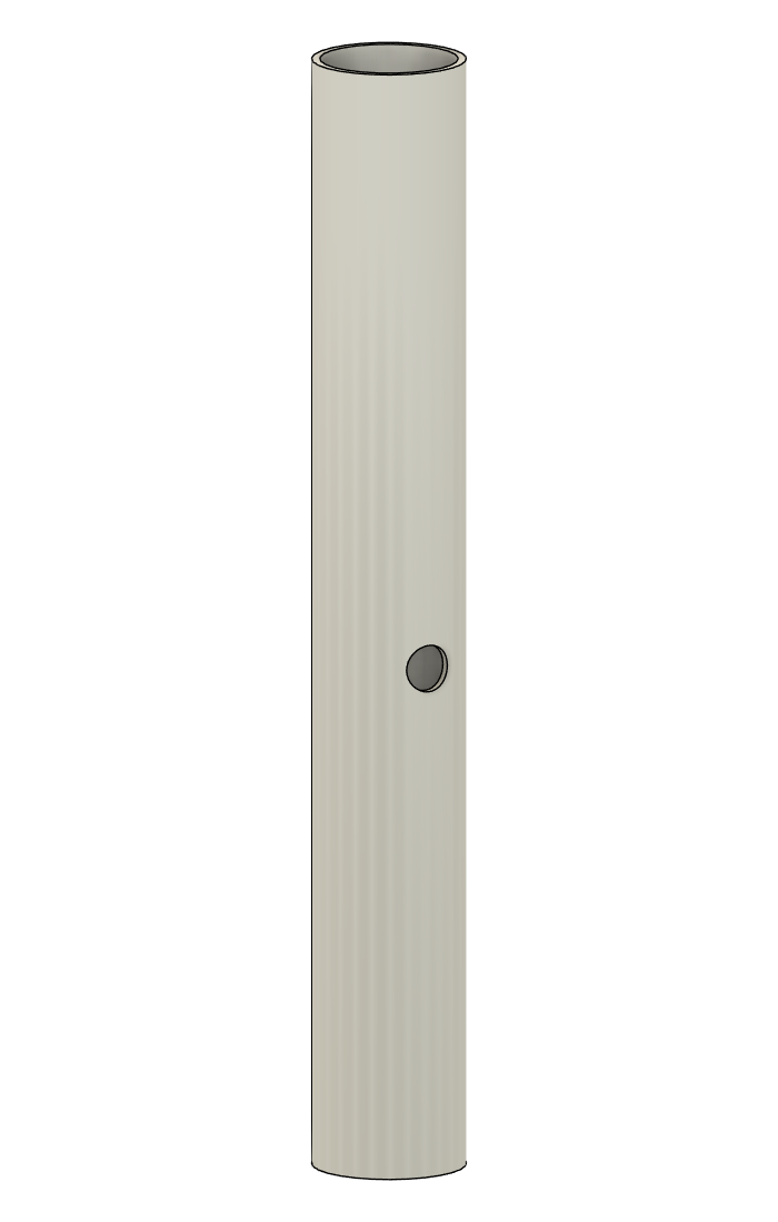
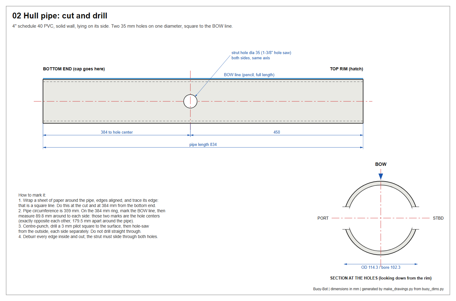
- Cut the pipe to 834 mm. Wrap a sheet of paper round the pipe with its edges lined up and trace along the edge: that line is square to the pipe. Saw on the waste side and file the end flat.
- Deburr both ends, inside and out, and file a 2 mm bevel on the outside of each (the cap and the hatch slide on more easily).
- Draw the BOW line. Lay the pipe on a flat table against a straight board and run a marker along the board's edge, end to end. Write BOW at both ends, BOTTOM at one end and TOP at the other.
- Mark the stub holes. Wrap the paper round the pipe 384 mm from the bottom end and trace a ring. The pipe is 359 mm around: measure 89.8 mm round the ring from the BOW line, in each direction. Those two marks are the hole centres. They are also 179.5 mm apart round the far side — check it.
- Drill. Centre-punch both marks. Drill a 3 mm pilot at each, square to the surface. Cut each 35 mm hole with the hole saw from the outside, one side at a time, at slow speed with light pressure, clearing the chips often.
- Deburr the holes inside and out.
Tips
- Do not saw both holes in one pass through the pipe: the saw wanders.
- PVC melts and grabs if the saw runs fast. Slow and light.
- A hole 1–2 mm out of position is harmless; the epoxy fillet in step 4
takes it up.
Check
Step 2 — Bottom cap, skirt disc and eye bolt
Time: 30 min. You need: 4" sch40 slip cap; 6 mm HDPE sheet; 316 stainless eye bolt 1/4" × 2-1/2" with one plain nut, two fender washers and one nylon-insert lock nut; marine sealant; primer and cement.
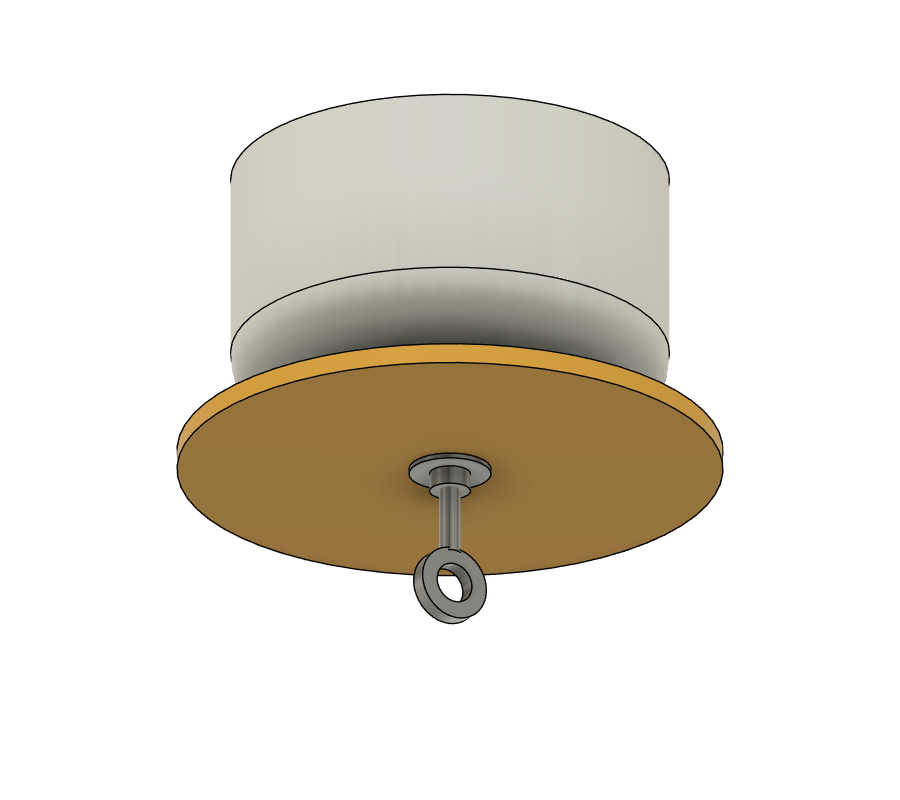
The eye bolt is the carry point and the tether point. The disc under the cap damps bobbing in boat wake.
- Cut the skirt disc. Scribe a 160 mm circle on the HDPE, cut it with the jigsaw, smooth the edge and drill 6.5 mm through the centre.
- Drill the cap 6.5 mm through the centre of its dome (the moulding mark shows the centre).
- Assemble the hardware, from the outside in: eye bolt → plain nut run up to the eye → fender washer → skirt disc → a ring of sealant → cap → a ring of sealant → fender washer → lock nut. Tighten until the disc cannot be turned by hand.
- Weld the cap to the pipe's BOTTOM end. Dry-fit first: the cap goes on about 51 mm; pencil a ring on the pipe at that depth. Prime the pipe end and the cap socket. Apply cement to both, push the cap on with a quarter turn until it reaches the ring, and hold it for 30 seconds — it tries to push itself back off. Wipe off the bead.
The inner lock nut stays exposed for now. In step 15 the ballast epoxy buries it, and after that the eye bolt can never work loose.
Check
Step 3 — Pod end caps
Time: 1 h, then 24 h cure. You need: both thruster pods; two 1" sch40 slip caps; 16 AWG silicone wire, six 700 mm lengths; four #2 × 1/2" stainless screws; epoxy putty; slow epoxy; masking tape.
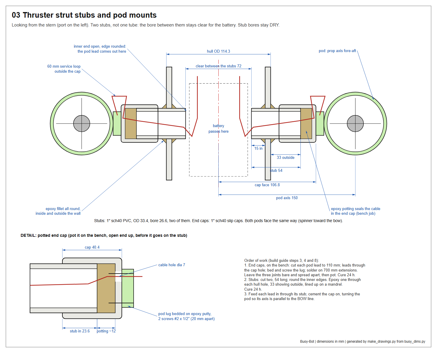
Each 1" cap does three jobs: it closes the end of a strut stub, it is the pad the pod screws to, and it seals the pod's cable. The cable seal is a pool of epoxy cast over the bare soldered joints between the pod's leads and their extensions. Epoxy grips tinned copper far better than it grips insulation, and a soldered joint stops water creeping along inside the strands, so the joint itself is the water block.
Make two, one per pod.
- Leads. Cut the pod's three leads to 110 mm. Cut three 700 mm extensions. Mark both ends of each extension A, B, C.
- Prepare the cap. Sand the inside of the socket and the outside of the dome until dull. Drill a 7 mm cable hole through the dome, about 10 mm off centre. Hold the pod's mounting lug against the dome, mark its two holes (2.3 mm, 20 mm apart) and drill 1.6 mm pilots.
- Mount the pod. Pass the three leads in through the cable hole, leaving a 60 mm loop of lead outside between the lug and the hole. Press a pad of epoxy putty onto the dome, bed the lug flat into it, and drive the two #2 screws.
- Solder. Inside the cap, solder each lead to its extension. No heat-shrink. Bend the three joints apart so no bare metal is within 4 mm of any other, and so all three lie in the bottom 10 mm of the cap.
- Mask. Run masking tape round the inside of the socket with its lower edge 12 mm above the bottom. PVC cement will not bond to a wall that has epoxy on it.
- Pot. Hold the assembly with the cap's open end up (rest the pod across a mug). Press a little putty round the cable hole on the outside so nothing runs out. Pour slow epoxy 12 mm deep and no deeper — the stub needs the other 24 mm of socket. Look straight down and confirm no two joints touch.
- Peel the tape when the epoxy gels. Leave 24 hours.
Tips
- The 60 mm outside loop is for the future: a replacement pod can be
spliced on there without disturbing the seal.
- If your pod's leads leave the lug's mounting face rather than its
side, drill the cable hole between the two screw holes instead.
- Check the joint spacing before you pour. The motor windings connect
the three leads at low resistance, so a meter cannot find a short afterwards.
Check
Step 4 — Strut stubs
Time: 45 min, then 24 h. You need: 1" sch40 PVC pipe; slow epoxy; epoxy putty; the dowel; masking tape.
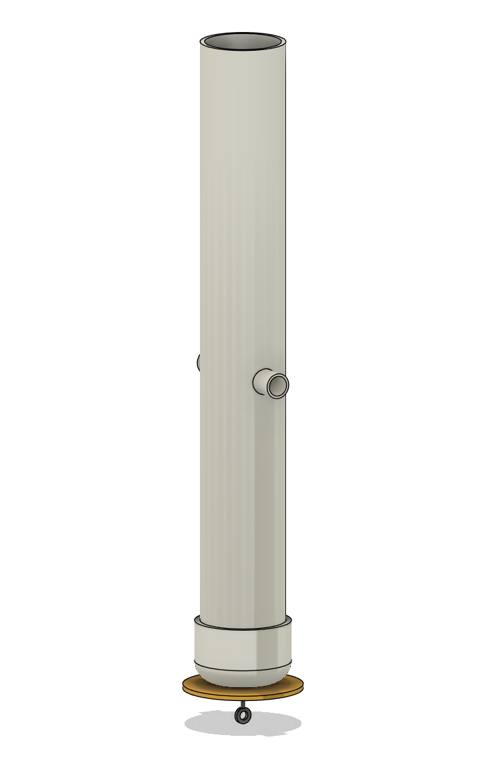
The thrusters hang on two short stubs of 1" pipe, one through each side of the hull (drawing 03, in step 3). There is no tube across the middle: the battery packs, 64 mm thick, have to pass between the stubs, and they leave 72 mm clear. Each stub is also the conduit for its pod's cable. Its bore stays dry, closed at the outer end by the potted cap from step 3 and open at the inner end, inside the hull.
- Cut two stubs, 54 mm long. Deburr them. On one end of each, round the inside edge with a file: that is the inner end, and the cable bends over it.
- Mark each stub with a pencil ring 33 mm from its outer end (the end that is not rounded).
- Prepare the surfaces. Sand each stub dull from the ring to its inner end. Sand the edges of both hull holes, inside and out. Wipe with alcohol.
- Make the mandrel. Wind two bands of masking tape round the dowel, about 150 mm apart, until a stub slides over each band without rattling. The mandrel holds the two stubs in line while the epoxy cures.
- Fit. Lay the hull on its side with the two holes left and right. Pass the mandrel through both holes. Butter the edge of one hole with mixed epoxy, slide a stub onto the mandrel, rounded end first, and push it into the hole until the pencil ring is flush with the outside of the hull: 33 mm shows outside, 15 mm projects inside. Do the same on the other side.
- Fillet. Knead epoxy putty and work a fillet all the way round each stub on the outside of the wall. Smooth it with a wet gloved finger. Then reach in with putty on the end of a stick and press a fillet round each stub on the inside. The outside fillet is the seal; the inside one adds strength.
- After an hour, when the putty is hard, pull the mandrel out. Leave the hull for 24 hours.
Tips
- Keep epoxy off the mandrel and out of the stub bores.
- The stubs do not have to be perfectly in line: the pods are aligned
later by turning their caps. Within a couple of degrees is plenty.
Check
Day 2 — steps 5 to 8. Bench work, then the pods are cemented on last.
Step 5 — Hatch cap
Time: 40 min. You need: Fernco QC-104 Qwik Cap; 3 mm polycarbonate; one 1/2" hose barb × 1/2" MIP nylon adapter; one 1/2" PVC female adapter (slip × FPT); bolt-in tyre valve; marine sealant.
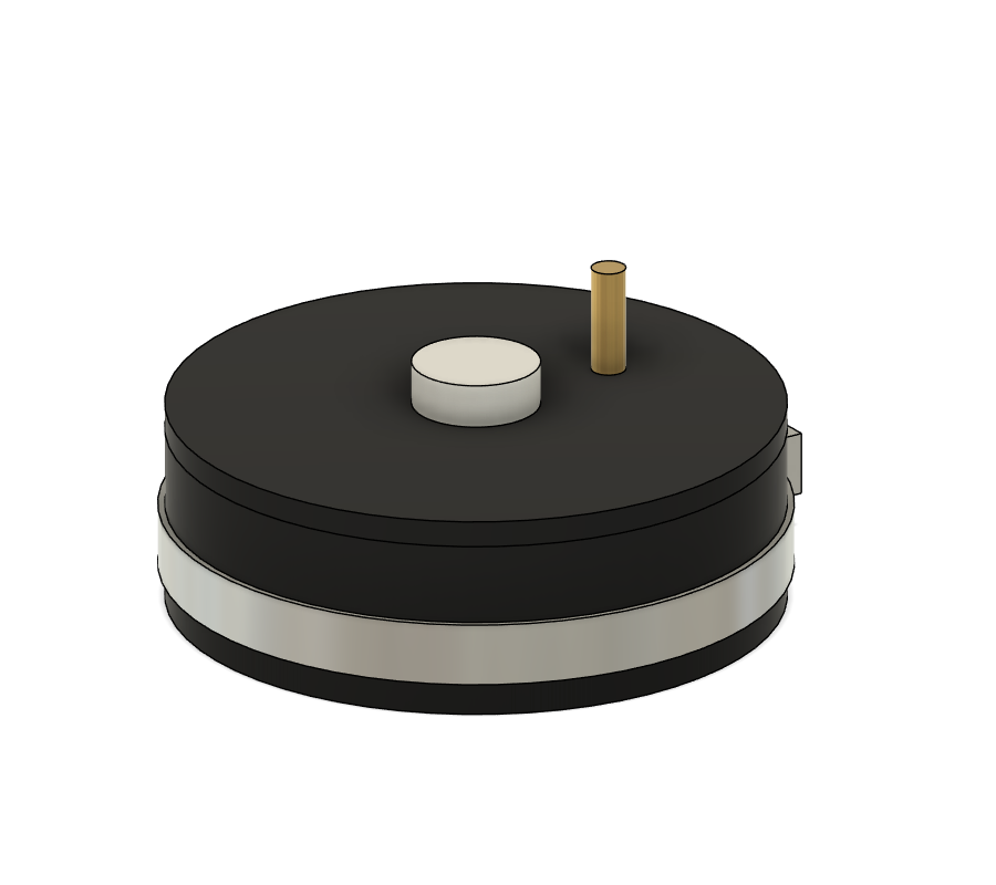
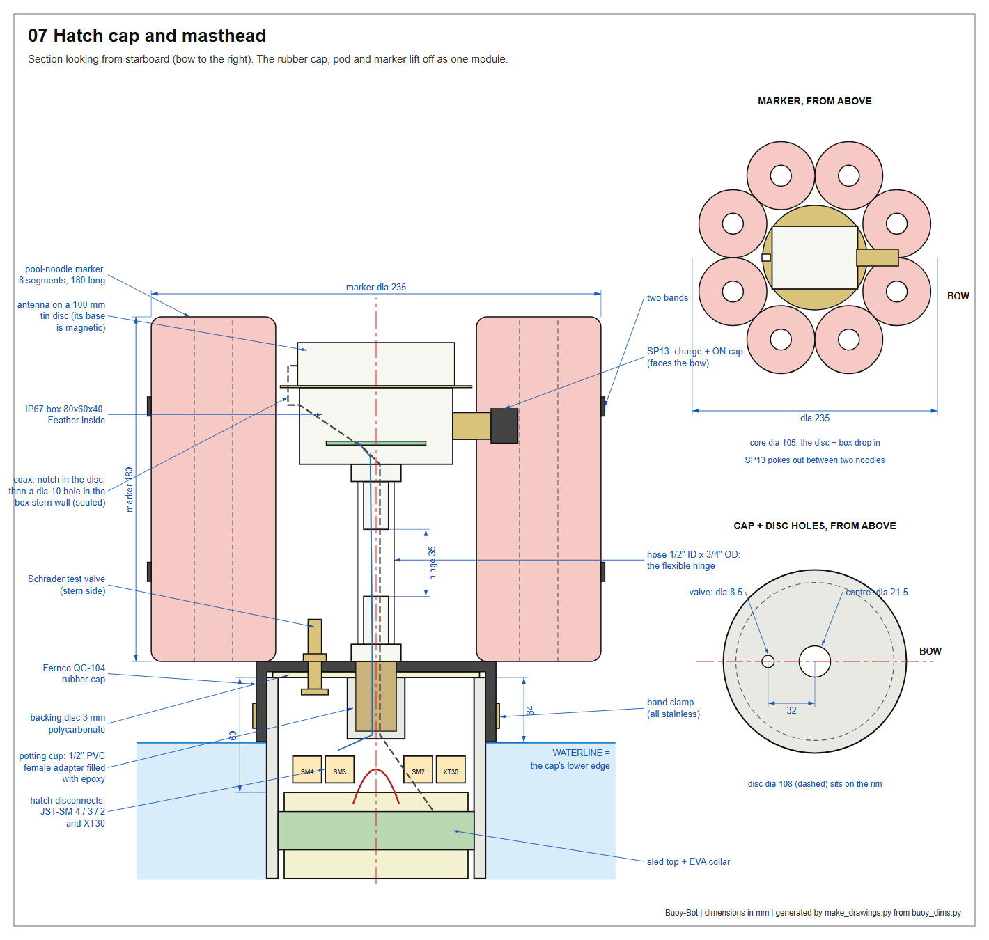
The hatch pushes straight on and is held by one band clamp. It never rotates, so nothing attached to it twists. A stiff disc inside the rubber rests on the pipe rim and gives the fittings something to clamp against.
- Backing disc. Cut a 108 mm disc from the polycarbonate. Drill 21.5 mm at its centre and 8.5 mm at 32 mm from the centre.
- Cap. Lay the disc inside the rubber cap as a template and cut matching holes through the rubber, slightly undersize: 20 mm and 8 mm. A sharp knife or a hollow punch works better than a drill.
- Mark the cap on the outside: BOW on the side away from the small hole. The valve sits toward the stern.
- Centre fitting. Push the barb adapter's thread in from the outside, through rubber and disc, with a thin smear of sealant under its hex. Screw the PVC female adapter onto the thread from the inside as the nut: hand tight plus a quarter turn. The rubber should be visibly squeezed under the hex.
- Valve. Fit the tyre valve in the small hole: grommet inside, stem outside, washer and nut snug.
- Magnet check. Hold a magnet to the band clamp. If the band or the screw housing pulls strongly, replace it with an all-316 marine clamp. The compass sits 90 mm below it.
The PVC adapter's open socket now hangs under the disc. It is the potting cup used in step 7.
Tips
- Pipe threads are tapered. If the adapter goes tight on the thread
before it clamps the rubber, put a plastic washer between the adapter and the disc.
- Do not grease the pipe rim or the inside of the cap, now or later.
The hatch stays on by friction.
Check
Step 6 — Electronics sled
Time: 3 h. You need: 6 mm HDPE sheet; assembled carrier PCB (rev B); GPS-RTK-SMA board; BMM150 compass; both ESCs; nylon M3 standoffs (5 mm) and screws; two 100 mm lengths of brass M3 threaded rod with four nuts and washers; two XT60 male plugs; 200 mm Qwiic cable; JST-XH 7-pin lead; JST-SM 2, 3 and 4-pin pairs; XT30 pair; inline blade-fuse holder with a 5 A fuse; 10 mm EVA mat; 3 mm cord; hook-and-loop tape; zip ties.
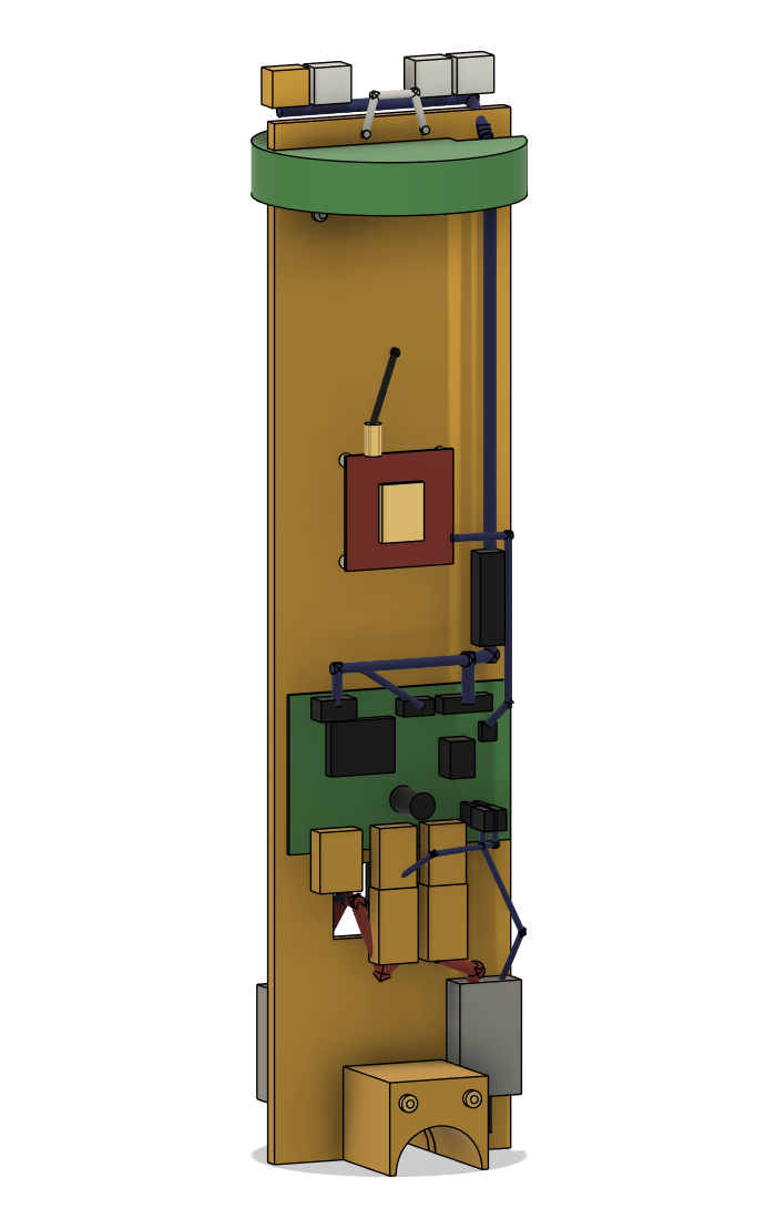
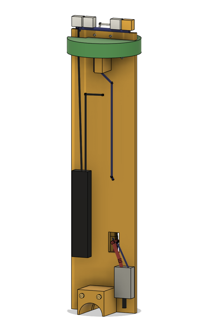
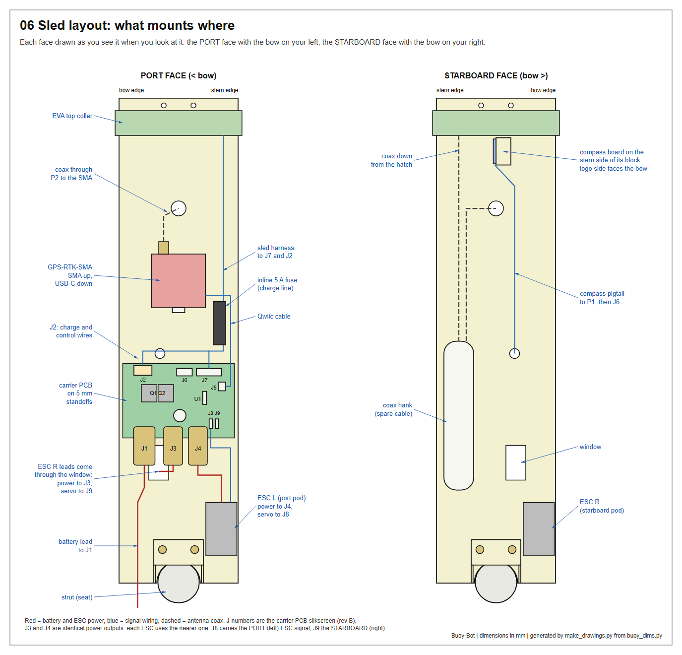
Before anything else, bench-check the carrier PCB as its README describes: with power on J1 and J2 terminals 3 and 4 bridged, the red LED lights and J7 pin 1 reads 3.30 V.
6.1 Plate and saddle
The saddle is a block at the foot of the plate, 90 mm wide, with a half-round notch along its underside. It drops over both strut stubs and bridges the gap between them. That one feature sets the sled's height and fixes its heading, so the compass always goes back at the same angle to the thrusters.
- Cut the plate 96 × 391 mm. Cut fourteen cheek pieces, 40 × 35 mm, from the offcut.
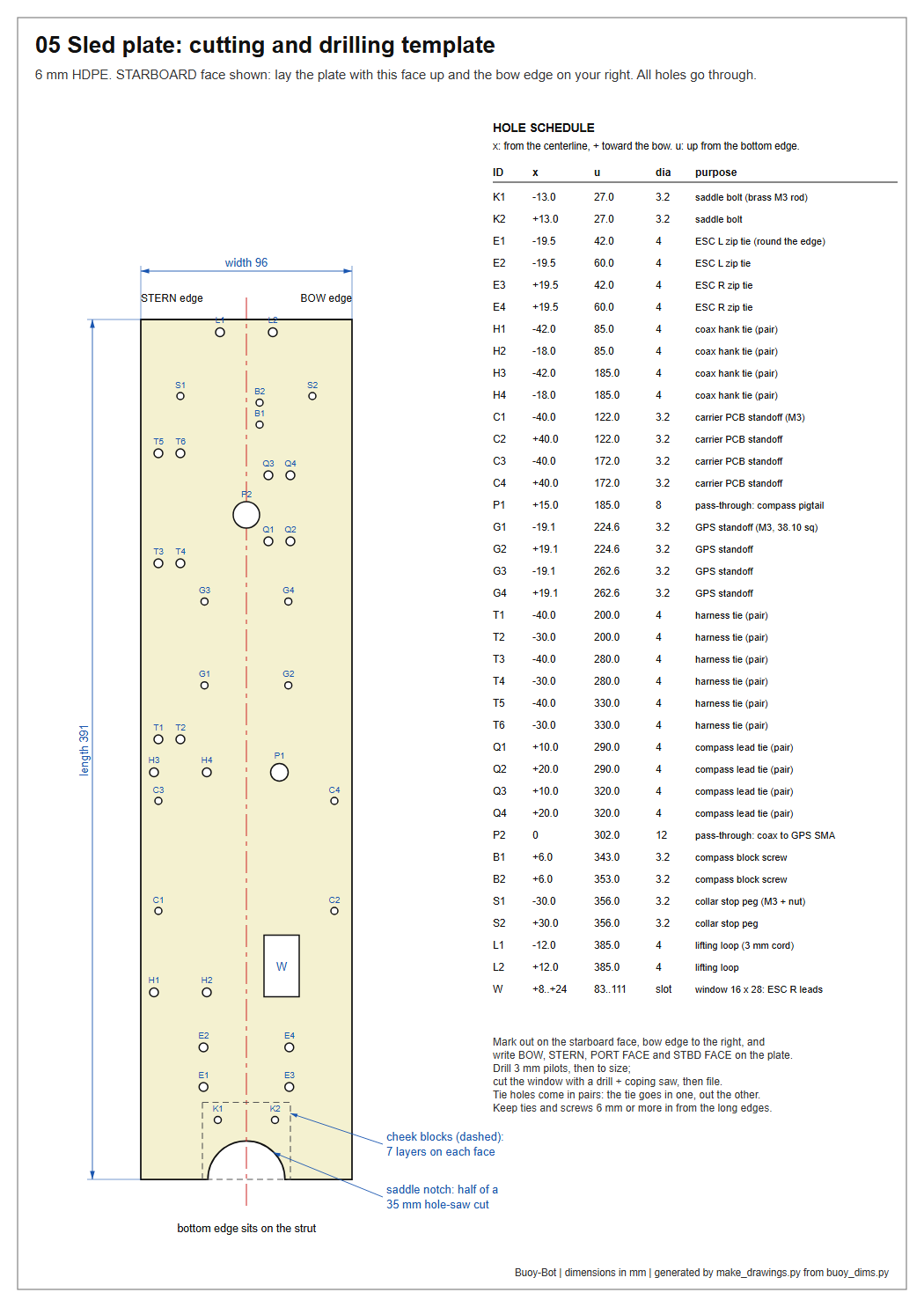
- Label the plate. Lay it flat with one short edge toward you: that is the bottom. Call the long edge on your right BOW and the one on your left STERN. The face looking up at you is the starboard face — write STBD FACE on it, and PORT FACE on the other side. This is exactly how drawing 05 is drawn.
- Drill the bolt holes. Drill K1 and K2 (3.2 mm) in the plate from the schedule on drawing 05. Using the plate as the template, drill the same two holes in every cheek, a few at a time, each cheek flush with the plate's bottom edge and centred on it.
- Cut the notches. The whole stack is 90 mm thick, far deeper than a hole saw, so cut it in sub-stacks: bolt three or four cheeks together (and, once, the plate with a cheek on each face), clamp a scrap board hard against their bottom edge, set the hole saw's pilot exactly on the bottom edge, at the centre, and cut.
- Assemble the saddle: seven cheeks on each face of the plate, on the two threaded rods, a washer and nut at each end. Tighten until nothing can shift.
- Trial-fit the saddle on the 1" pipe offcut. It should drop on and not rock.
- Holes. With the starboard face up and BOW to your right, mark the remaining holes from the schedule on drawing 05 (x from the centreline, plus toward the bow; u up from the bottom edge). Drill 3 mm pilots, then to size. Cut window W with a drill and coping saw and file it smooth.
6.2 Mount the parts
Turn the plate to look at each face in turn. Remember: at the port face the bow edge is on your left.
| Part | Face and position | How |
|---|---|---|
| Carrier PCB | port face, holes C1–C4 | four 5 mm nylon standoffs; components toward you; the three XT60s pointing down toward the saddle. J1 is then at the bow end |
| GPS-RTK-SMA | port face, holes G1–G4 | four 5 mm nylon standoffs; SMA connector up, USB-C down |
| ESC L (port pod) | port face, stern side, just above the saddle | hook-and-loop, plus two zip ties round the plate edge through E1 and E2; motor leads down, power and servo leads up |
| ESC R (starboard pod) | starboard face, bow side, just above the saddle | the same, through E3 and E4; pass its power and servo leads through window W to the port face |
| Compass | starboard face, on a block at B1 and B2 | cut the block 12 × 30 × 22 mm from two glued layers of HDPE; fix it with nylon screws; fix the compass board to the block's stern side, logo side against the block (so the logo faces the bow), "UP" edge up. Nylon screws only |
6.3 Wire the sled
- ESC power. Solder an XT60 male plug to each ESC's power leads, red to +, black to −, matching the + and − on the carrier's silkscreen. Plug ESC L into J4 and ESC R into J3. (J3 and J4 are the same output; each ESC uses the nearer one.)
- ESC signal. Push ESC L's servo plug onto J8 and ESC R's onto J9, signal (white) wire on the pin marked S. The middle pin is deliberately unconnected; it parks the ESC's unused red wire.
- GPS. Qwiic cable from the GPS board to J5.
- Compass. Run its pigtail down the starboard face (ties at Q1–Q4), through hole P1, and into J6 in the order 3V3, GND, SDA, SCL.
- Signal harness. Plug the 7-pin lead into J7. Join its wires 1–4 (3V3, GND, SDA, SCL) to the JST-SM 4 and wires 5–7 (PWM L, PWM R, VSENSE) to the JST-SM 3.
- Charge and control harness, from the J2 screw terminal on the carrier's top edge (terminal numbers are on the silkscreen):
- terminal 1 (CHG+) → the 5 A inline fuse → XT30, positive;
- terminal 2 (GND) → XT30, negative;
- terminal 3 (CTL) → JST-SM 2, pin 1;
- terminal 4 is not used.
- Dress the harness up the stern edge of the port face (ties at T1–T6). Tie the 5 A fuse holder to it just above the carrier (drawing 06), where it is more than 100 mm from the compass; magnet- test it first (a glass-fuse holder's spring is often steel). Leave the four connectors about 60 mm above the plate's top edge.
⚠ Compass wiring. On the existing bench unit the compass SDA wire is off its pad, and the firmware still reports "Compass: ok". Re-solder it now and confirm it in step 13.
6.4 Top collar and lifting loop
- Glue two layers of EVA and cut a 103 mm disc, 20 mm thick, with a 6 × 96 mm slot across it. Widen the stern end of the slot into a notch about 25 × 20 mm for the harness and the coax.
- Slide it onto the top of the plate, down to stop pegs fitted at S1 and S2 (an M3 screw and nut in each).
- Thread a loop of cord through L1 and L2 and knot it.
Tips
- Keep every tie and screw at least 6 mm in from the plate's long edges.
- The sled carries no steel. Check any hardware you substitute with a
magnet. That includes the two screws that bolt the carrier's FET tabs to the board: use brass M3 × 6.
- This guide assumes carrier rev B. A rev A board needs the changes
listed in the carrier README.
Check
Step 7 — Masthead
Time: 2 h, then 24 h cure. You need: IP67 box about 80 × 60 × 40; the second barb adapter and a nylon 1/2" locknut; 90 mm of 1/2" ID × 3/4" OD braided vinyl hose; two nylon hose clamps; SP13 socket and three plugs; 100 mm tin lid; the antenna; the Feather; hook-up wire (seven colours of 26 AWG, red and black 20 AWG, one 24 AWG, 600 mm each); the mating JST-SM 2, 3, 4 and XT30 halves; two red pool noodles; two 500 mm reusable zip ties; VHB tape; sealant; desiccant; slow epoxy; putty.
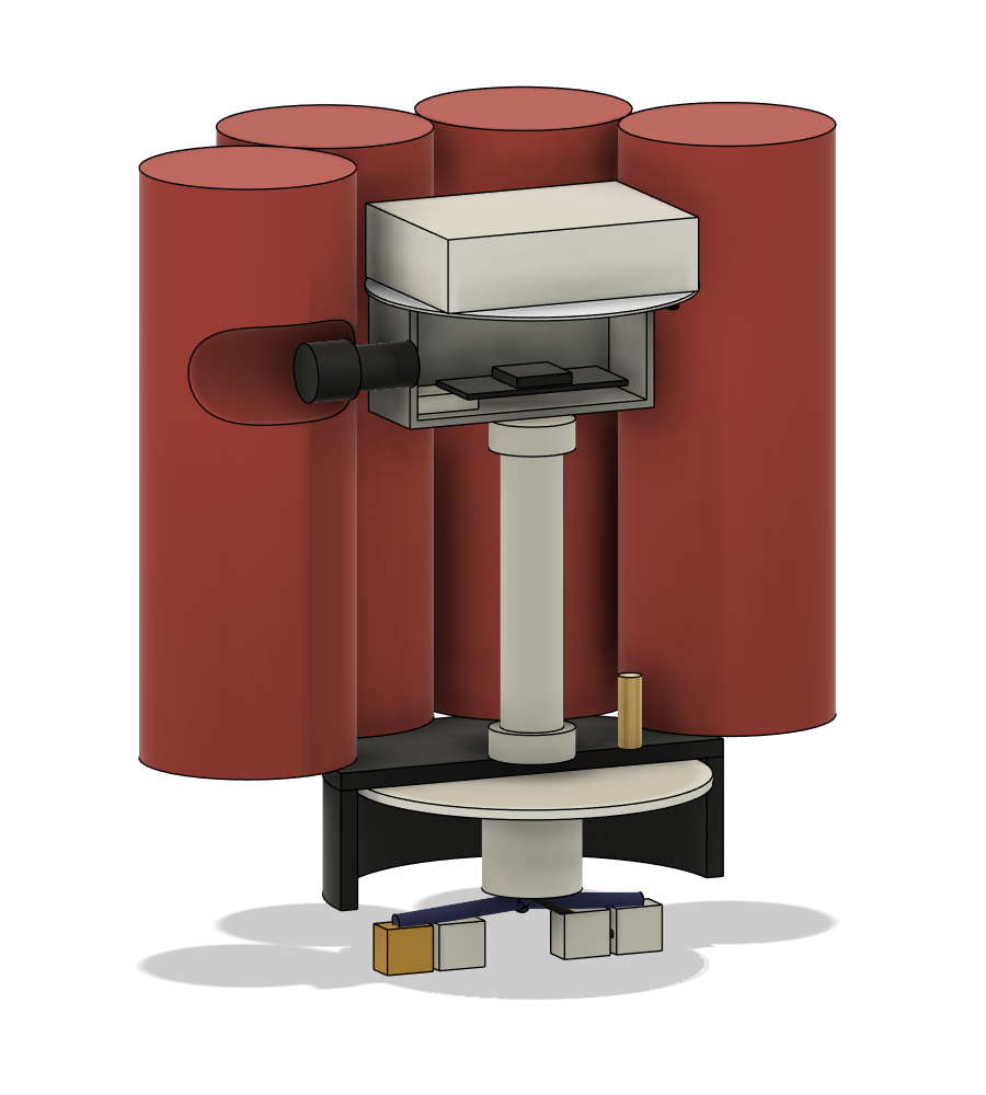
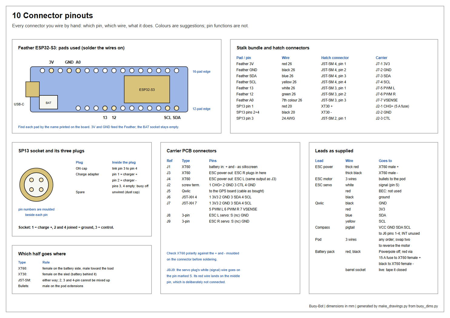
The masthead is built onto the hatch cap from step 5. Refer to drawing 07 (step 5) and the pinout sheet (step 6).
7.1 Pod box
- Drill the box: 21.5 mm in the centre of the bottom; 13 mm in the middle of one short end wall (the bow end, for the SP13); 10 mm in the opposite end wall, close under the lid (the stern end, for the antenna coax).
- Fit the barb adapter pointing down through the bottom, locknut inside, sealant under the hex. Use a plastic washer if the nut binds on the taper before it clamps.
- Fit the SP13 socket with its gasket.
7.2 SP13 and its plugs
- Socket: pin 1 → red 20 AWG (charge +). Pins 2 and 4 joined → black 20 AWG (ground). Pin 3 → the 24 AWG wire (control). Pin numbers are moulded beside the pins.
- ON cap: a plug with pins 3 and 4 linked.
- Charge adapter: a plug with pin 1 to the charger's + and pin 2 to its −; pins 3 and 4 empty.
- Keep the third plug as a spare. Label all three.
7.3 Antenna
- Snip a notch about 6 × 6 mm in the edge of the tin lid and cover the cut edge with tape. Bare tin will saw through coax.
- Stick the tin lid to the box lid with VHB tape, notch toward the stern.
- Set the antenna on it, cable end toward the stern. Its magnetic base holds it.
7.4 Thread the stalk
- Try the coax's SMA plug in a barb adapter. It needs a 10 mm bore; open both adapters with a 10 mm drill if it is tight.
- Push the hose onto the pod's barb and clamp it.
- Feed the SMA plug through the notch, in through the box's stern hole, down through the pod fitting, the hose, the cap's barb fitting, and out through the potting cup. Pull all the coax through.
- Feed the ten wires down the same way.
- Push the hose onto the cap's barb until 35 mm of hose shows between the two barbs, and clamp it. That free length is the flexible hinge.
- Seal the coax hole in the box wall with sealant.
7.5 Feather
- Solder the seven 26 AWG wires to the Feather's pads: 3V, GND, SDA, SCL, 13, 12, A0. Record the colours.
- Fix the Feather in the box with foam tape, USB-C reachable with the lid off. Leave its battery socket empty.
- Add a desiccant sachet, smear the lid gasket lightly with silicone grease, and close the lid.
7.6 Pot the hatch fitting
- Turn the assembly over so the inside of the cap faces up, masthead hanging below (the rim of the bucket holds it).
- Where each wire will lie inside the potting cup, strip a 5 mm band of insulation and tin it. Stagger the bands up and down the cup so no two bare spots can touch. Scuff the coax jacket there with sandpaper.
- Pack a pea of putty into the bottom of the cup around the wires so liquid epoxy cannot run down into the hose.
- Fill the cup with slow epoxy. Leave 24 hours.
This plug is what keeps the hull sealed if the masthead is ever torn off.
7.7 Pigtail connectors
About 250 mm from the cup, fit the mating JST-SM 4, JST-SM 3, JST-SM 2 and XT30 halves, wire for wire with the sled's (pinout sheet, step 6). The coax continues unbroken.
7.8 Marker
- Cut eight 180 mm lengths of red pool noodle.
- Stand them in a ring round the pod; the tin lid drops into the 105 mm space in the middle.
- Carve a notch in the two bow-side noodles so the SP13 shows between them.
- Cinch the ring with the two long zip ties at about one-quarter and three-quarters of its height. The marker rests on the rubber cap, and its top stands about 13 mm above the antenna.
Tips
- Any closed-cell foam about 235 mm across and 180 mm tall can replace
the noodle ring; bore the same 105 mm core.
- The antenna's magnets are part of what the compass calibration
learns. The BOW mark on the cap makes sure the masthead always goes back the same way round.
Check
Step 8 — Fit the pods to the stubs
Time: 30 min, then 24 h. Not before: 24 h after steps 3 and 4. You need: the two potted end caps; primer and cement; six 3.5 mm male bullet plugs; heat-shrink.
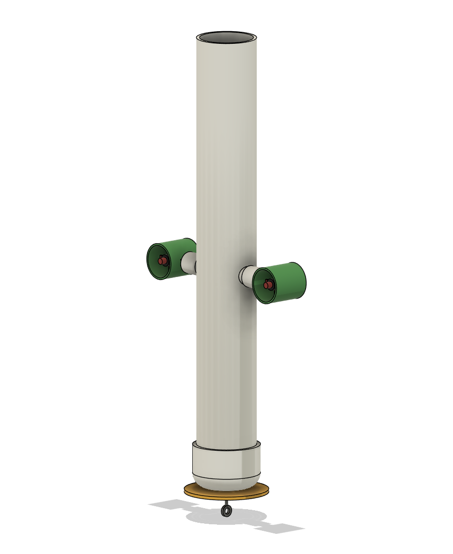
Do one side at a time.
- Feed the cable. Push the three extension wires in through the stub from outside. They drop into the hull: hook them up to the rim with the bent wire.
- Dry-fit the cap on the stub. Turn the pod until its propeller axis is parallel to the BOW line and its spinner cone points to the bow. Pencil a witness mark across cap and stub.
- Cement. Prime the stub end and the cap socket, apply cement to both, push the cap fully home, line up the mark, and hold for 30 seconds.
- Repeat on the other side. Both pods face the same way.
- Bullets. Solder a male bullet to each of the six extension ends and cover the joints with heat-shrink. Label the two bundles PORT and STBD and tape them over the rim.
Check
Day 3 — steps 9 to 14. Not before 24 hours after step 8.
Step 9 — Pressure test #1
Time: 30 min. Not before: 24 h after steps 7 and 8.
This tests the empty hull and the hatch together, before anything goes inside.
- Push the hatch on until the disc sits on the rim, BOW mark over the BOW line. Set the band clamp about 15 mm above the cap's lower edge and tighten it firmly with the nut driver.
- Pump through the valve: two or three strokes of a floor pump, to 0.1 bar (1.5 psi). The rubber face just begins to dome. Stop there.
- Spray soapy water on: the bottom-cap seam; the eye bolt; both stub fillets; both pod end caps (weld line, cable hole, screw heads); the valve; the centre fitting; the cap's lower edge.
- Wait 10 minutes.
To fix a leak: mark it, release the pressure, dry it, sand it, and add epoxy putty (joints) or re-seat the part (clamp, fittings). Wait for the repair to cure and test again.
Check
Release the pressure and take the hatch off.
Step 10 — Ballast, first fit (loose)
Time: 30 min. You need: lead shot; six small zip bags; the luggage scale and the kitchen scale.
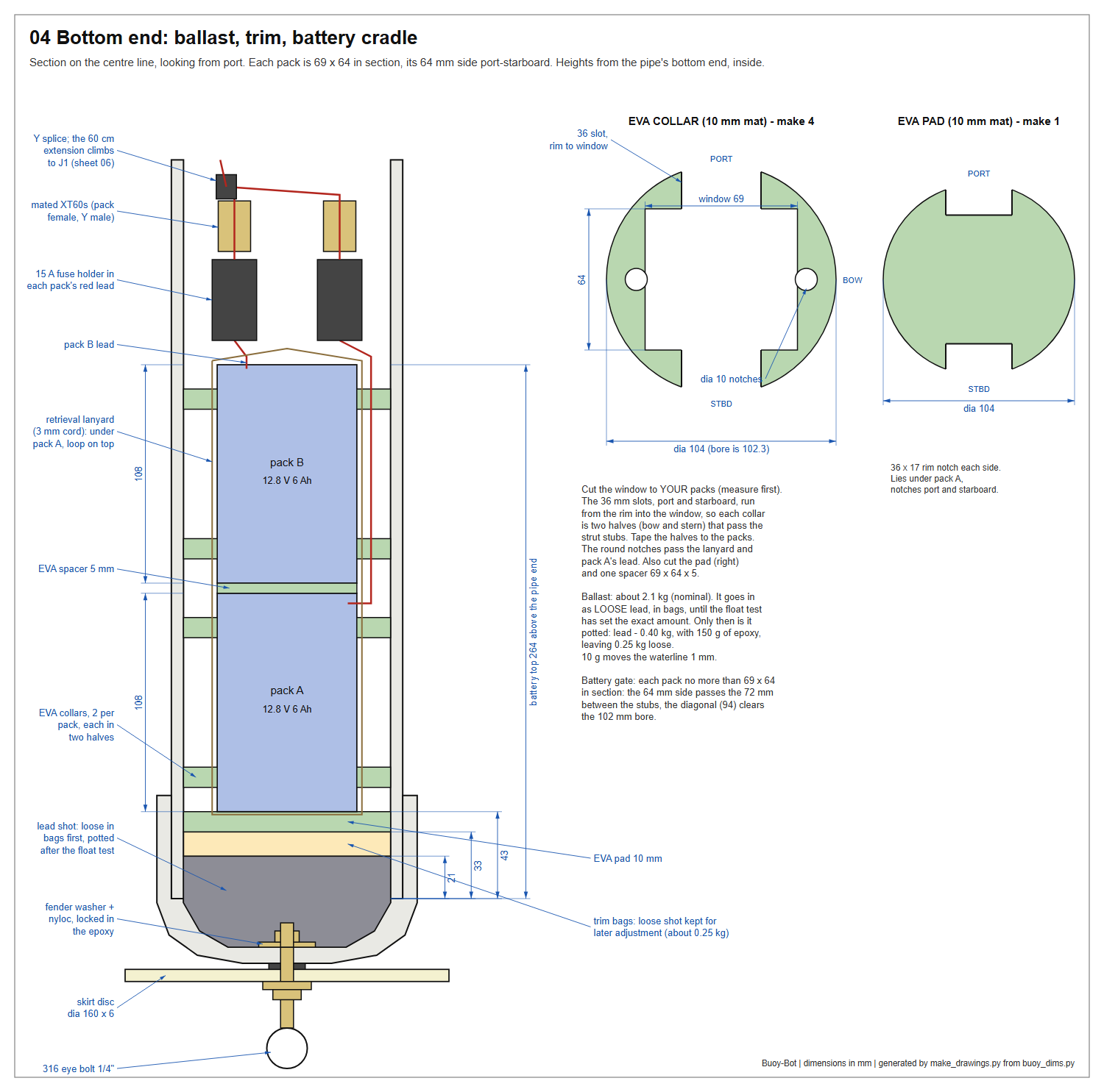
The buoy floats at the right height only at one all-up weight: about 9.0 kg by the design calculation. How much of that must be lead depends on what everything else really weighs — and several weights in the calculation, the battery packs above all, are catalogue estimates. So the lead goes in loose now, is corrected in the water at step 14, and is potted only afterwards, at step 15.
- Weigh everything except lead. Use the luggage scale, and add the figures up:
- the hull as it stands (pipe, cap, stubs, pods);
- the sled, complete;
- the hatch and masthead, complete with marker;
- both battery packs with the fused Y-harness and the 60 cm extension;
- the EVA collars and pads, the cord, two desiccant sachets.
The design figure for this total is 6.9 kg.
- First ballast = 9.0 kg minus your total. The design figure is 2.1 kg. Write yours down.
- Bag it. Weigh that much shot into four to six zip bags, each inside a second bag, air squeezed out. Keep the bags flat and no more than 60 mm wide so they pass between the strut stubs.
- Load it. Lower the bags to the bottom and tamp them flat and level with the dowel.
Tips
- Bag weights you can combine are useful at the float test: for example
four of 500 g, plus 200 g, 100 g and 50 g.
- Do not be tempted to pot the lead now to save a day. Once it is in
epoxy, the only correction left is whatever is still loose.
Check
Step 11 — Battery
Time: 45 min, plus charging. You need: two Bioenno BLF-1206A 12.8 V 6 Ah LiFePO4 packs (a stock item); two XT60 female plugs; two inline blade-fuse holders for 12 AWG with 15 A fuses; XT60 Y-harness; 60 cm XT60 extension; 12 AWG silicone wire if a lead needs lengthening; 10 mm EVA mat; 1.6 m of 3 mm cord.
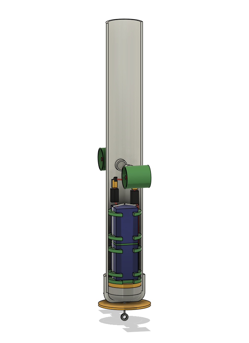
The collar and pad shapes are on drawing 04 (step 10). The packs go down between the two strut stubs, which is why each collar is slotted on its port and starboard sides. Bioenno does not recommend running its packs in parallel unless they are matched and fused, so both are done here.
- Gate check. Measure each pack over its wrap with calipers: no more than 108 × 69 × 64 mm. Its 64 mm side then passes the 72 mm between the stub tips, and its section diagonal (94 mm) clears the 102 mm bore. A substitute pack must also charge through its main lead (on the Bioenno, the charge socket and the main lead share one protection board).
- Charge and match. Charge both packs fully on the bench, then measure them: within 0.1 V of each other before they are ever joined.
- Leads. On each pack, cut off the Anderson Powerpole (Bioenno allows changing the connector; never open the pack) and fit, working away from the pack: a 15 A fuse holder in the red lead, then a female XT60, red to +. Pack A's lead climbs past pack B, so it must reach about 150 mm beyond its pack: lengthen it with 12 AWG if it is short. Tape the barrel charge socket closed and tuck it along the pack: it is live.
- Cut the EVA (drawing 04):
- four collars: 104 mm discs with a window the size of your packs' cross-section, a 10 mm round notch in the middle of each 64 mm side of the window (the lanyard and pack A's lead run through these), and a 36 mm slot in the middle of each 69 mm side, from the rim right into the window. Each collar falls into two halves;
- one 104 mm pad with a 36 × 17 mm notch in its rim on each of two opposite sides;
- one pack-sized spacer, 5 mm thick.
- Lanyard. Lay the middle of the cord under pack A and tape it up its two 64 mm faces.
- Build the stack on the bench: pack A, leads up, with collar halves taped round it 12 and 86 mm up from its bottom end; the spacer; pack B with its collars at the same heights. Line up all the slots. Bring pack A's lead and the lanyard tails up through pack B's round notches, and knot the lanyard in a loop above pack B.
- Join. Plug both packs into the Y-harness and the 60 cm extension into the Y. In the hull, the fuse holders, the XT60 joints and the Y splice lie above pack B and below the stubs (drawing 04).
- Lower it in. Drop the pad to the bottom, notches facing port and starboard. Lower the stack by the lanyard with its slots facing port and starboard too, so they pass over the stubs. The 69 mm width then runs bow to stern, and the leads and lanyard come up at the bow and stern sides.
- Press the stack home with the dowel on a collar, never on the wiring. Tape the extension's free end over the rim.
Check
Step 12 — Final assembly
Time: 30 min.
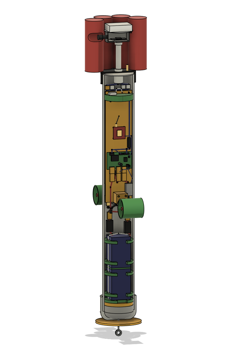
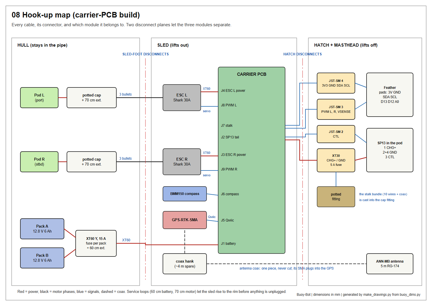
- Coax. Lay the masthead beside the sled. Wind the spare coax into a flat hank about 120 mm long — round three fingers, gentle bends, no kinks — and tie it to the starboard face, stern side (ties H1–H4). Pass the SMA plug through hole P2 and screw it onto the GPS board: finger-tight, then a slight nip.
- First power-up, sled out. Stand the hull in its bucket. Hold the sled just above the rim and hang the masthead on a chair back.
- Plug the PORT bullets into ESC L's motor leads and the STBD bullets into ESC R's.
- Plug the battery extension into J1.
- Join the four hatch connectors.
- Fit the ON cap. The carrier's red and green LEDs light and both ESCs chirp. Take the ON cap off again.
- Lower the sled. Feed the loops of slack down ahead of it. Lower the sled by its cord with its port face to port and its BOW edge toward the BOW line, until the saddle drops over the two stubs. The motor leads come out of the stub ends underneath the saddle: let them hang down and out to the bow or stern side before they rise.
- Witness check. The top edge of the plate is 60 mm below the rim, and the sled cannot be turned. If it sits high, a wire is trapped on a stub: lift, shake the loops down, and lower again.
- Close. Fold the pigtail and connectors onto the top collar. Add a desiccant sachet. Push the hatch on until the disc seats on the rim, BOW mark over the BOW line, and tighten the clamp with its screw at the stern.
Check
Step 13 — Bench test
Time: 30 min. Fit the ON cap and connect from the app over Bluetooth.
| Send | Expect |
|---|---|
command:version | the firmware line. Battery: none is normal; GNSS: ok |
command:i2cscan | 0x42 (GPS) and 0x13 (compass) both answer |
command:escdiag | both ESCs attached |
command:thrust:20, then command:stop | both propellers blow air toward the stern |
command:thrust:-20, then command:stop | both blow toward the bow |
- A propeller blows the wrong way: swap any two of that pod's
bullets.
- Nothing happens on the negative command: that ESC does not reverse.
The bundled ESC manual has no setting for it (the fitted ESCs were verified to reverse on 2026-10-05), so replace it with a bidirectional ESC (HARDWARE.md names two).
- Keep dry runs to a few seconds.
Stop check. A bidirectional ESC sets its neutral band when it arms, and the band may not be centred on the pulse the buoy sends for stop.
- Send
command:stop. Within a few seconds both propellers must be still. - If one keeps turning, note which way. Step that ESC's trim (
trlfor the left,trrfor the right) by 2 µs at a time, opposite in sign to the creep: forward creep, negative trim. For examplecommand:gains:trl=-2, then-4, and so on, sendingcommand:stopafter each change. - Note the first trim at which it is still, then keep stepping until it starts turning the other way. Set the trim halfway between the two: the middle of the ESC's neutral band.
- Check that
command:thrust:20andcommand:thrust:-20still turn it both ways, thencommand:gains:save.
Charge test. Take the ON cap off and fit the charge adapter. The charger shows that it is charging and the buoy stays off.
Thrust curve. Out of the box the firmware limits each thruster to tmax = 75 µs from idle, which may give only a few percent of the pod's rated pull. Measure before raising it:
- Put one pod under water in a tub and tie the hull to the luggage scale, in line with the thrust. The other pod runs dry: a few seconds per setting only.
- Allow the higher settings:
command:gains:tmax=350. The firmware ceiling is 400. - For each of 75, 150, 250 and 350: send
command:thrust:N, read the scale once it steadies, thencommand:stop. Write each pull down. - Choose the lowest setting that gives the pull you need, with margin. On this hull, holding station in a current takes about 0.3 N per pod at 0.1 m/s, 1.1 N at 0.2 m/s and 2.5 N at 0.3 m/s (estimates; drag rises with the square of the current). Set
tmaxthere, withsmaxabout three-quarters of it (the default ratio is 55 to 75), for examplecommand:gains:tmax=250,smax=185. The firmware never letssmaxexceedtmax. command:gains:save. After a power cycle,command:gainsreports the new values.
The curve also sets the SURGE_* gains: they scale inversely with the pull per microsecond.
Check
Step 14 — Seal test, compass and float trim
Time: 2 h.
- Pressure test #2, through the valve, as in step 9. The hull is now full of parts and needs fewer strokes: stop as soon as the cap's face starts to dome. Soap the cap's lower edge, the centre fitting, the valve and both pod end caps.
- Compass calibration. Outdoors, away from cars and steel benches, with the masthead fitted. The firmware has no calibration routine yet (it reads the raw field); this step is a placeholder until one is written, and no heading should be trusted before then.
- Weigh the buoy on the luggage scale by its eye bolt and write the figure down.
- Float test, in calm water at least 1.2 m deep, on a retrieval line. Target: floating upright, waterline at the lower edge of the rubber cap, ± 10 mm.
- Trim. Measure how far the waterline is from the cap's lower edge. Each millimetre is 10 g: floating high, add lead; floating low, take lead out. Open the hull (appendix A), change the bags, close it and float it again. Two rounds are usually enough.
- Soak. When the waterline is right, leave the buoy floating for 30 minutes, then open it and look for water.
- Record the result: the all-up weight, and the total lead on board. These two numbers are what step 15 uses.
Tips
- Trim with everything aboard exactly as the buoy will be used: marker,
ON cap, desiccant, the lot.
- A flooded hull sinks. Keep the retrieval line and a small float on
the eye bolt for the float test and the first few outings.
Check
After the float test — step 15. One evening to pot, a day to cure, an hour to reassemble.
Step 15 — Pot the ballast, final checks, first water
Time: 45 min, 24 h cure, then 1 h. Not before: step 14 is passed. You need: the lead from the float test; about 150 mL slow-cure epoxy; two wads of foam; a paper funnel.
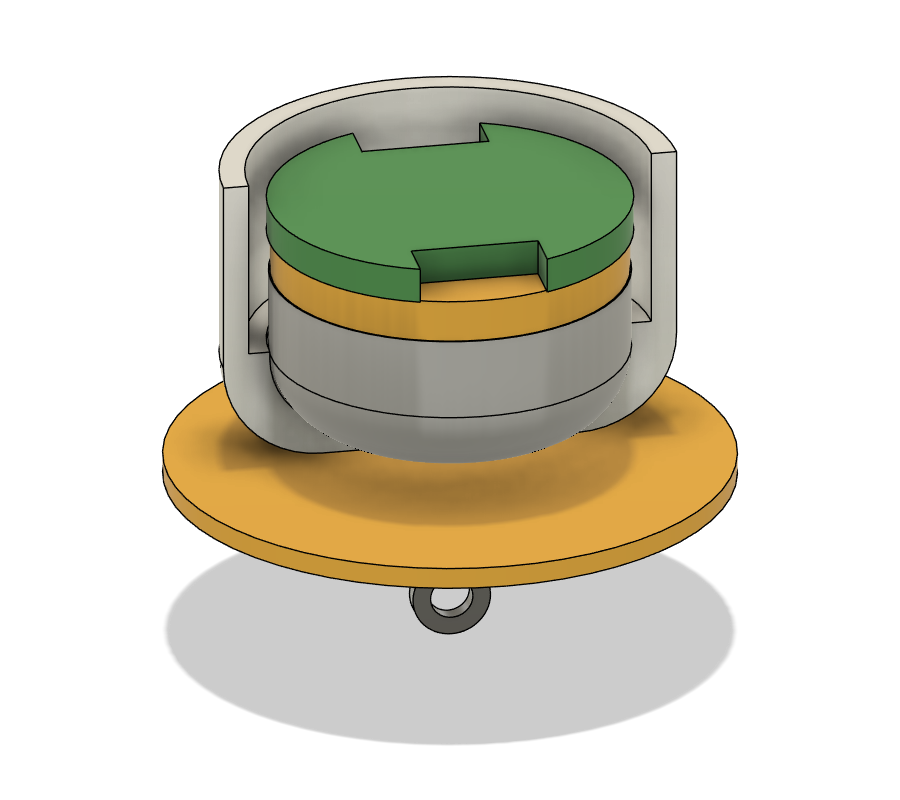
Now that the float test has fixed the amount, most of the lead is bonded into the bottom cap so it cannot shift, and so the eye bolt's inner nut is locked for good. A little stays loose for future changes.
- Strip the hull (appendix A): sled out, battery out, every bag of lead out. Wipe the inside dry.
- Work out the amounts. Weigh all the lead that came out; call it L.
- Lead to pot = L − 0.40 kg.
- 0.15 kg of that difference is replaced by the epoxy itself;
- 0.25 kg stays loose, as trim bags.
With the design figure L = 2.1 kg, that is 1.7 kg to pot.
- Protect the cables. Tape the motor leads up over the rim. Push a wad of foam into the open inner end of each stub, around the wires, so no shot or epoxy can get in.
- Pour the shot. Stand the hull, eye bolt down, in a bucket padded with rags, and lash it so it cannot tip. Empty the bags of lead to be potted through a paper funnel. Tap the pipe until the surface is level.
- Pour the epoxy. Mix 150 g of slow epoxy, by weight. Pour it in a thin stream down the bow side of the wall — away from the stubs — in two or three goes, tapping the hull between pours, until a wet film just covers the shot.
- Leave the hull upright for 24 hours. Then pull out the foam wads.
- Reassemble. Put the 0.25 kg of loose lead back as trim bags, then the battery and sled as in steps 11 and 12.
- Confirm. Weigh the buoy: it should be within 20 g of the float- test figure. If it is not, correct the trim bags. Repeat pressure test #2, since the hatch has been off.
Tips
- Use slow epoxy. Five-minute epoxy heats up in this volume and sets
before it has flowed through the shot.
- If more than about 30 g of epoxy is left in the cup, the buoy is that
much lighter than planned: add it to the trim bags as lead.
Check
First-water checklist
Appendix A — Opening it up
- ON cap off. Loosen the clamp, lift the hatch about 150 mm, and unplug the four hatch connectors.
- Lift the sled by its cord until the battery plug and the bullets are at the rim. The masthead stays joined to the sled by the coax: hang it on something, or unscrew the SMA plug at the GPS board to separate them.
- Unplug the XT60 and the six bullets, and lift the sled away.
- Battery: pull the lanyard. Turn the stack so its collar slots pass the stubs.
- Trim bags: hook them out with the bent wire.
Reassemble as in steps 11 and 12. Charging and switching on never need the hull opened: both are done at the SP13 on the masthead.
Appendix B — Routine checks
Before each launch
- Clamp firm; hatch seated all round; valve cap on.
- Marker bands tight; stalk upright.
- Propellers turn freely; no line or weed in the ducts.
- ON cap fitted last; both ESCs chirp.
After each outing
- ON cap off. Rinse the pods with fresh water.
- Charge through the SP13.
Each season, and after any knock
- Pressure test (step 9).
- Open the hull: look for water, swap both desiccant sachets.
- Inspect the rubber cap for cracks or chalking; replace it if in doubt.
- Check the stub fillets and pod end caps for cracks.
- Re-check the compass calibration if anything on the sled or masthead
was changed.
- Re-weigh and re-trim if anything was added, removed or replaced.
- Store the packs at about half charge, indoors, over winter.
Appendix C — Building without the carrier PCB
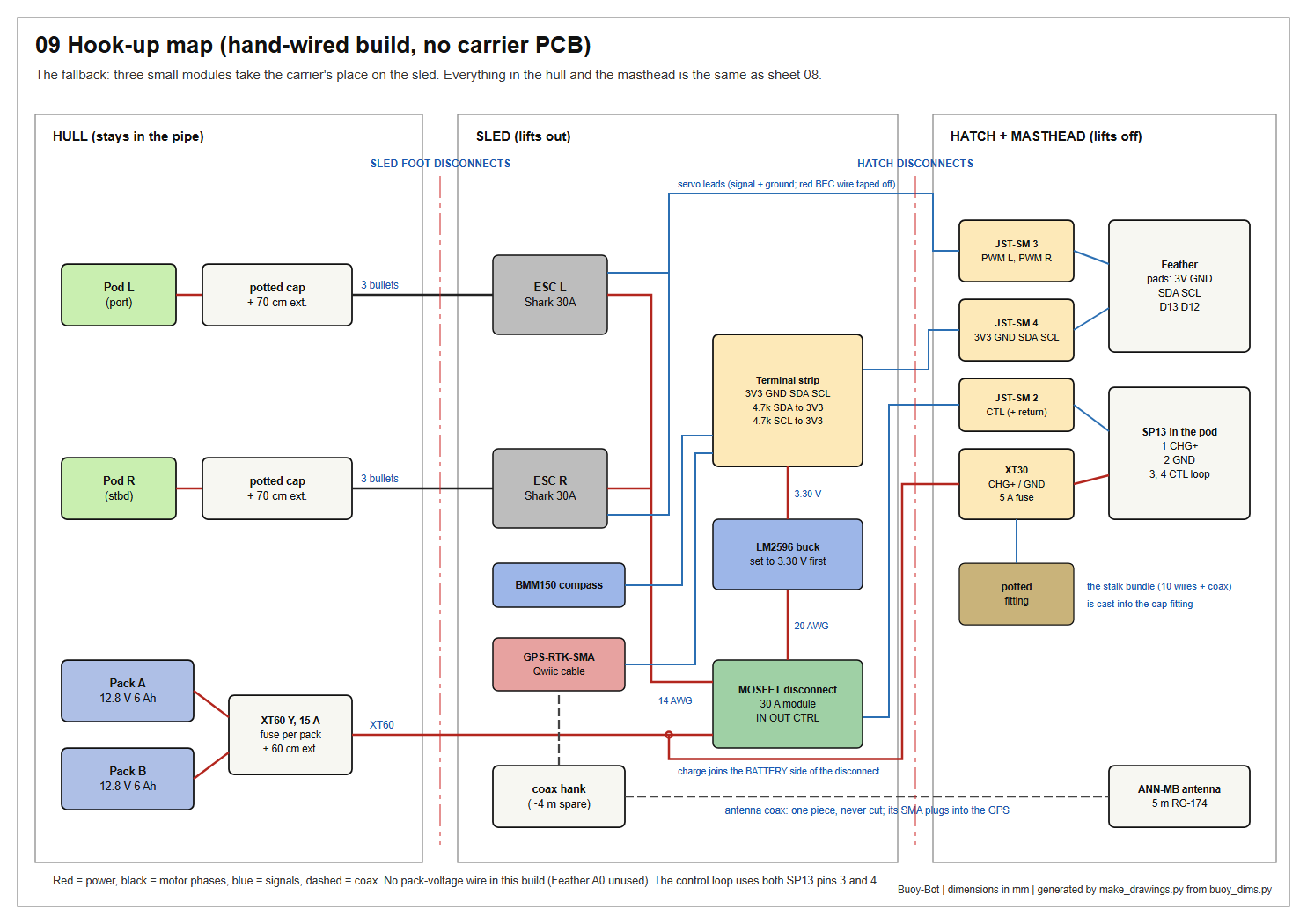
The sled has room at the carrier's position for three modules that do the same job: a 30 A MOSFET disconnect module, an LM2596 buck converter, and a 4-way terminal strip carrying two 4.7 kΩ I²C pull-up resistors. Wire them as WIRING_GUIDE.md §6 describes. Three things differ from the main build:
- Set the buck converter to 3.30 V on the bench before it is ever connected to the Feather.
- The control loop uses both SP13 pins 3 and 4, on two separate wires. Do not join pin 4 to pin 2.
- The ESC power leads are soldered to the module's output instead of plugging in, and there is no pack-voltage wire: Feather pad A0 stays unconnected.
Everything else in this guide is unchanged.
Appendix D — Troubleshooting
| Symptom | Likely cause | Remedy |
|---|---|---|
| Pressure falls but no bubbles are found | valve core, or the cap's lower edge | soap the valve tip; re-seat the cap and re-tighten the clamp |
| Bubbles at a stub fillet | pinhole in the putty | dry, sand, add putty, cure, re-test |
| Bubbles at a pod end cap's cable hole | potting did not wet a lead | dry, work slow epoxy into the hole from outside, cure, re-test |
| Battery will not go down, or jams at the stubs | collar slots not lined up with the stubs | turn the stack so the slots face port and starboard |
| Thrusters cut out a few seconds into hard thrust | a pack's protection board tripped: each pack allows 12 A continuous | lower tmax; reset the packs by fitting the charge adapter for a few seconds |
| Sled sits high | a wire lying on a stub | lift 100 mm, shake the loops down, re-seat |
| Floats tilted | battery or trim bags off centre | re-seat the stack; lay the bags flat |
| Floats high or low | real weights differ from the design figures | trim: 10 g per millimetre (step 14) |
| Heading wanders with throttle | compass wiring fault, or power wiring near the compass | check command:i2cscan; keep all power leads below the carrier |
| Heading is 180° out | sled seated with its port face to starboard | lift it, turn it round, re-seat |
| No GNSS fix with the marker on | wet foam over the antenna | keep the core open above the antenna; test dry first |
| One propeller pushes the wrong way | two motor phases swapped | swap any two bullets on that pod |
| ESCs do not chirp | ON cap not making contact, or battery plug off J1 | check the cap's link; check J1; look for the carrier's LEDs |
Appendix E — Dimensions on one page
| Item | Value |
|---|---|
| Hull pipe | 4" sch40, 834 long (OD 114.3, bore 102.3) |
| Stub holes | 35 dia; centres 384 from the bottom end; 89.8 round the pipe from the BOW line, each way |
| Strut stubs | two, 1" sch40, 54 long; 33 showing outside, 15 inside; 72 clear between them |
| Pod end caps | 7 dia cable hole; 12 of epoxy; 60 loop of lead outside |
| Pods | axes 150 from the hull's centre line, 300 apart |
| All-up weight | about 9.0 kg (design figure; the float test decides) |
| Ballast | about 2.1 kg of loose lead at the float test (design figure). Afterwards: potted = that lead − 0.40 kg, with 150 g of epoxy; 0.25 kg kept loose |
| Battery | two stock 12.8 V 6 Ah LiFePO4 packs (Bioenno BLF-1206A), each 108 × 69 × 64, on end with a 5 spacer; 64 side port-starboard; top of the stack about 570 below the rim; 15 A fuse in each pack's lead |
| Battery collars | four, 104 dia, bottoms 12 and 86 up each pack; 69 × 64 window; 36 slot each side, rim to window (each collar is two halves). Pad: 104 dia, 36 × 17 rim notch each side. Spacer 69 × 64 × 5 |
| Sled plate | 96 × 391 × 6; top edge 60 below the rim when seated |
| Saddle | 90 wide: seven 40 × 35 × 6 cheeks on each face; half-round notch from the 35 hole saw |
| Hatch | Fernco QC-104; disc 108 dia × 3; holes 21.5 at the centre and 8.5 at 32 |
| Stalk | 90 of 1/2" ID hose; 35 showing between the barbs |
| Marker | eight 180 lengths of 65 dia noodle; 235 across; top about 13 above the antenna |
| Waterline | at the rubber cap's lower edge; pipe rim 34 above the water; 10 g moves it 1 mm |
| Pressure test | 0.1 bar (1.5 psi) for 10 minutes; hand pump only |